Replaces the traditional silo hammer: always effective in cases where a hand hammer could be used.
Durable, robust and easy to maintain
Effective single impacts: maximum impact effect with minimum weight
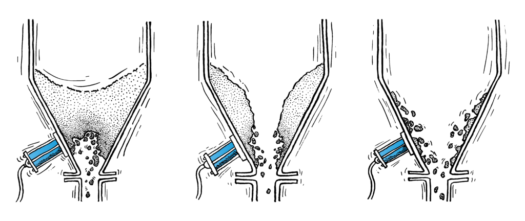
Reliable removal in containers & silos of:
Product residues
Caking
Shaft formation
Bridging
Vibrates in a decaying manner: no vibration cracks
No imbalance as with vibrators
No self-resonance
This is because the knocker is only used when it is truly needed: maximum effectiveness with the greatest possible material protection! This relieves the strain on the weld seams, which would otherwise fatigue with constant vibration oscillations.
The knocker is normally controlled by an electrical control system with a solenoid valve. Within the area where the knocking takes place there should be enough space for the impact to expand in all directions.
Reinforcements of the silo walls and additional ribs should be avoided, as this increases the weight and the strength of the silo walls and thus reduces the effect of the knocker.
The Pneumatic Knocker produces an ideal elastic shock that is specified as the impact energy [Nm] and as impulse [Ns]. There is no impact force or imbalance such as vibrators generate.
The effectiveness of the knocker is evaluated according to the following rule:
If the product can be knocked off or made to flow with a hand hammer, the Pneumatic Knocker is also effective.
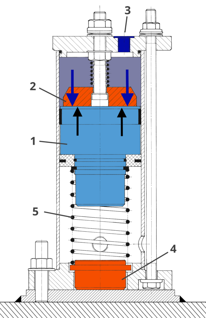
Construction & Functioning
With pneumatic singold magnet system knockers, a very high impact work is achieved through spontaneously released stored compressed air energy.
In Figure, the knocker is shown in section.
The magnetic impact piston (1), designed as a permanent magnet, adheres to the anchor plate (2) in the basic position by means of magnetic force (↑).
Compressed air is supplied through the connecting thread (3).
After a short time, the pressure force (↓) overcomes the magnetic force and the magnetic impact piston suddenly detaches itself from the anchor plate.
It is accelerated very forcefully by the stored compressed air and hits the striker bolt (4) with a speed of 6 to 7 m/s.
The striker bolt transmits the impact via the welding plate directly to the silo wall.
After venting the knocker, the spring (5) pushes the magnetic impact piston back into its initial position.
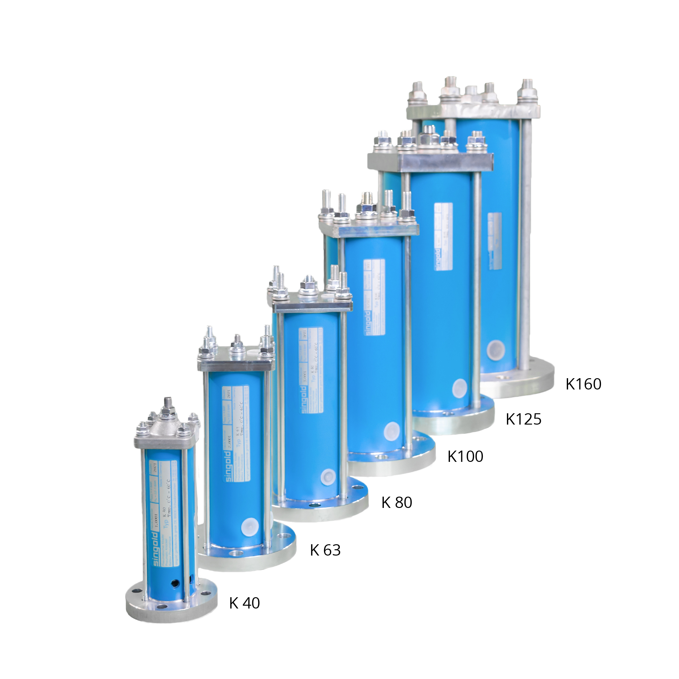
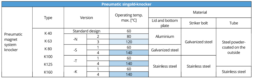
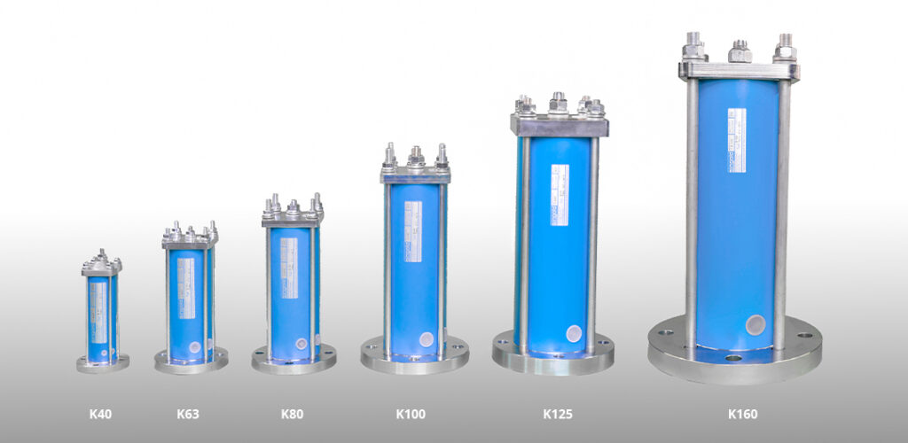
Versions & Selection Chart
Our knockers are available in the following versions. Simply select the version that suits your needs using our handy online configurator. For more complex applications, please use our online questionnaire.
The selection chart below provides a rough reference for selecting the adequate size and number of Pneumatic Knockers for round silos of 60° cone. In the case of rectangular containers, a minimum of two knockers are mounted on the flatter sides.
Move your cursor to the desired section (smartphone users will need to click):
Key factors to consider when choosing the right knocker are:
Thickness of the container’s sheet metal
Container material
Container diameter
Operating temperature
If present, insulation thickness for the selection of the mounting
Choice of version in aluminium, steel or stainless steel
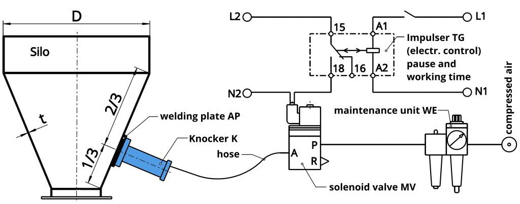
Mounting & Operation
For the assembly and operation of the pneumatic knocker, the components shown in the picture are required:
Attaching the Pneumatic Knocker Welding plate AP.
With small pipes, small containers or containers with insulation welded plate in T-shaped APT
Pneumatic 3/2 way solenoid valve in the desired control voltage.
Electrical control for solenoid valve to desired control voltage. An existing PLC control can also be used.
Pneumatic connectors and cables
Maintenance unit for pressure reduction to 3.5 bar operating pressure, drainage and lubrication of the knocker is recommended.
The surface to be knocked should be able to swing, so that the impact can spread to all sides. Reinforcements of the silo walls and additional ribs are to be avoided, as this increases the weight and strength of the silo walls and reduces the impact of the knocker.
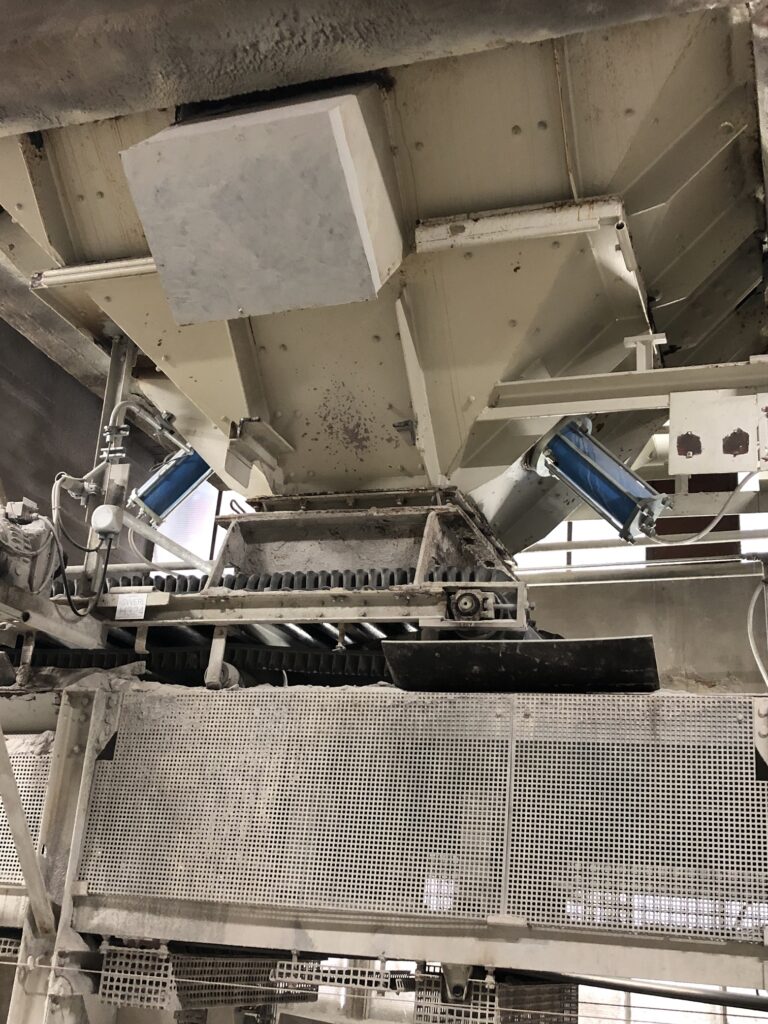
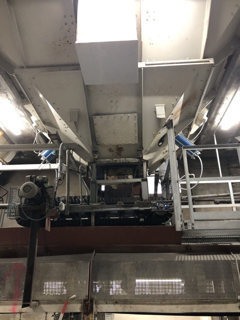
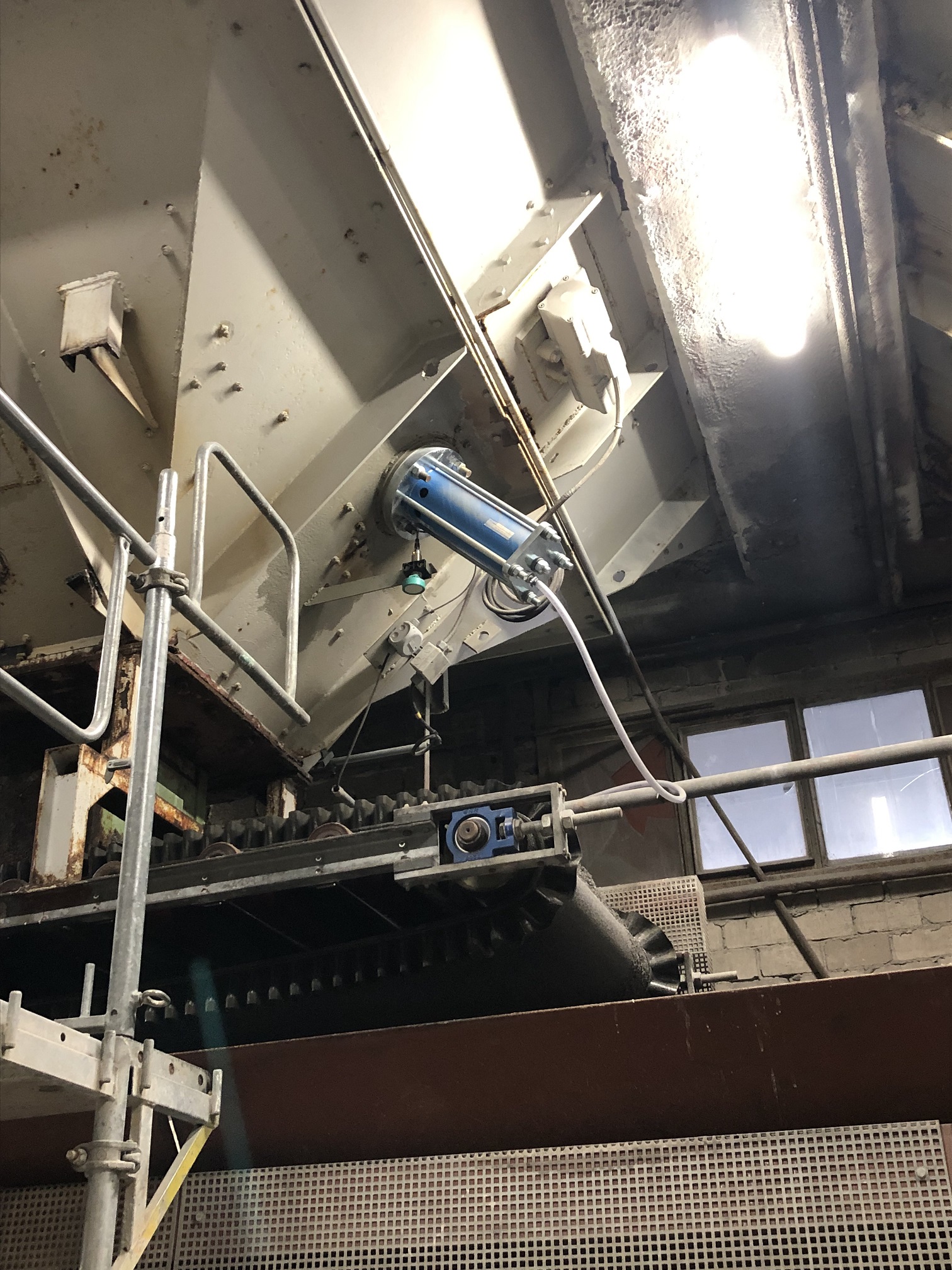
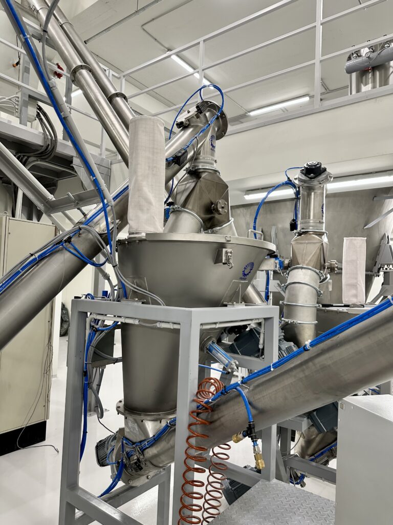
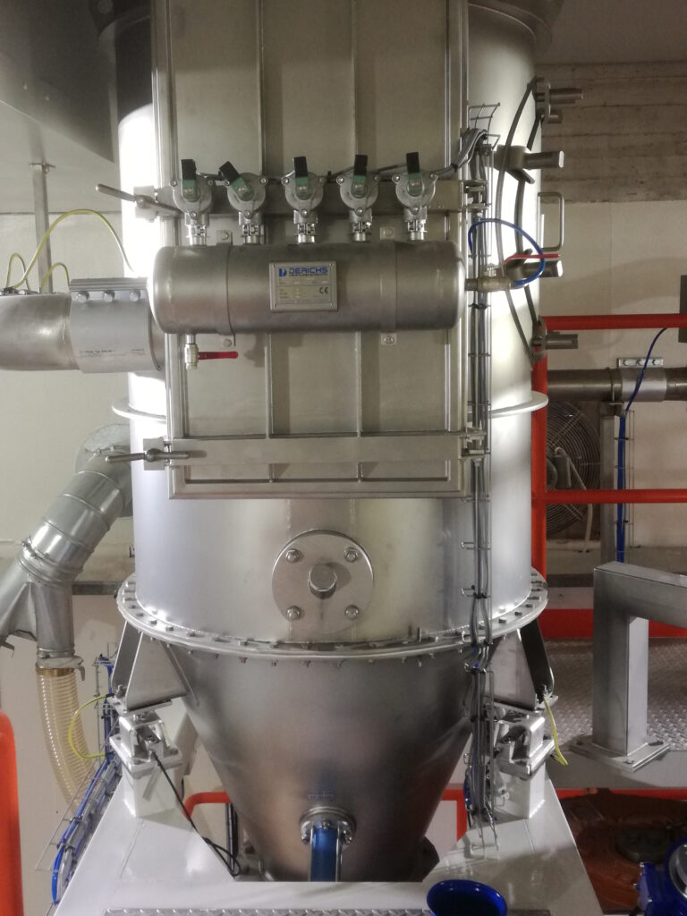
2x K160 on a rectangular gravel bunker outlet (4 x 4 m) made of 20 mm sheet steel. The hammer marks from the time before the singold knockers were installed are clearly visible.Another bunker outlet measuring 4 x 4 m. Here, too, two K160 units were installed. The K160, the world’s largest knocker, has a net weight of 62 kg and a height of approximately 0.5 m.Close-up of one of the retrofitted K160 units below one of the originally installed vibrators, which had remained unsuccessful.Also popular in the food industry: Here is our smallest model, the K40, mounted on a container above a screw conveyor.Plant manufacturer Derichs also relies on singold knockers. Who can find the knocker in the picture? 🙂
Questionnaire
Fill in the fields as required – if not relevant, you can skip them.